This web site contains links to source code, builds and documentation for a suite of complementary software projects that implement the core functions of an electronic monitoring (EM) platform for commercial fisheries. All of these projects are open source and released under the GPL. Development started in 2016 and has been funded primarily by several National Fish and Wildlife Foundation grants along with contributions from Sea State Inc, Saltwater Inc and Chordata LLC. Initial work on the video analysis components was also funded by United Catcher Boats and the Midwater Trawlers Cooperative. System requirements, design, development and testing were performed by:
- Chordata LLC (Stephen Mell, Jubal Skaggs and Eric Torgerson)
- Saltwater Inc (Nancy Munro, Kathryn Carovano, Jared Fuller and Morgan Wealti)
- Sea State Inc (Karl Haflinger)
Platform
- Supports full EM data life cycle
- Designed with simple, text based interfaces between components
- Simple interfaces allow for easy integration with other
open source (or proprietary) components such as:
- Machine learning models
- Data archival solutions such as Amazon Glacier or Google Cloud Platform
- Well suited to integration into a production data environment - easily export data as CSV or JSON
Key Technologies
- Cross platform C++ using QT SDK
- IP camera control using Open Network Video Interface Forum
- Configuration and message passing using Google Protocol Buffers
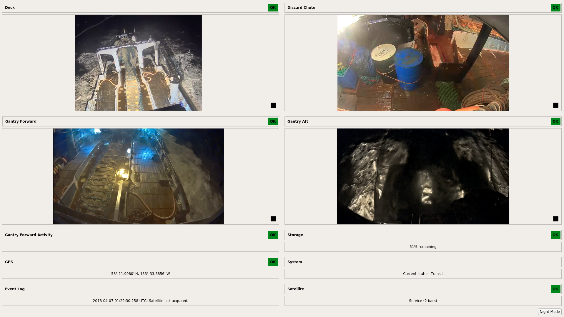
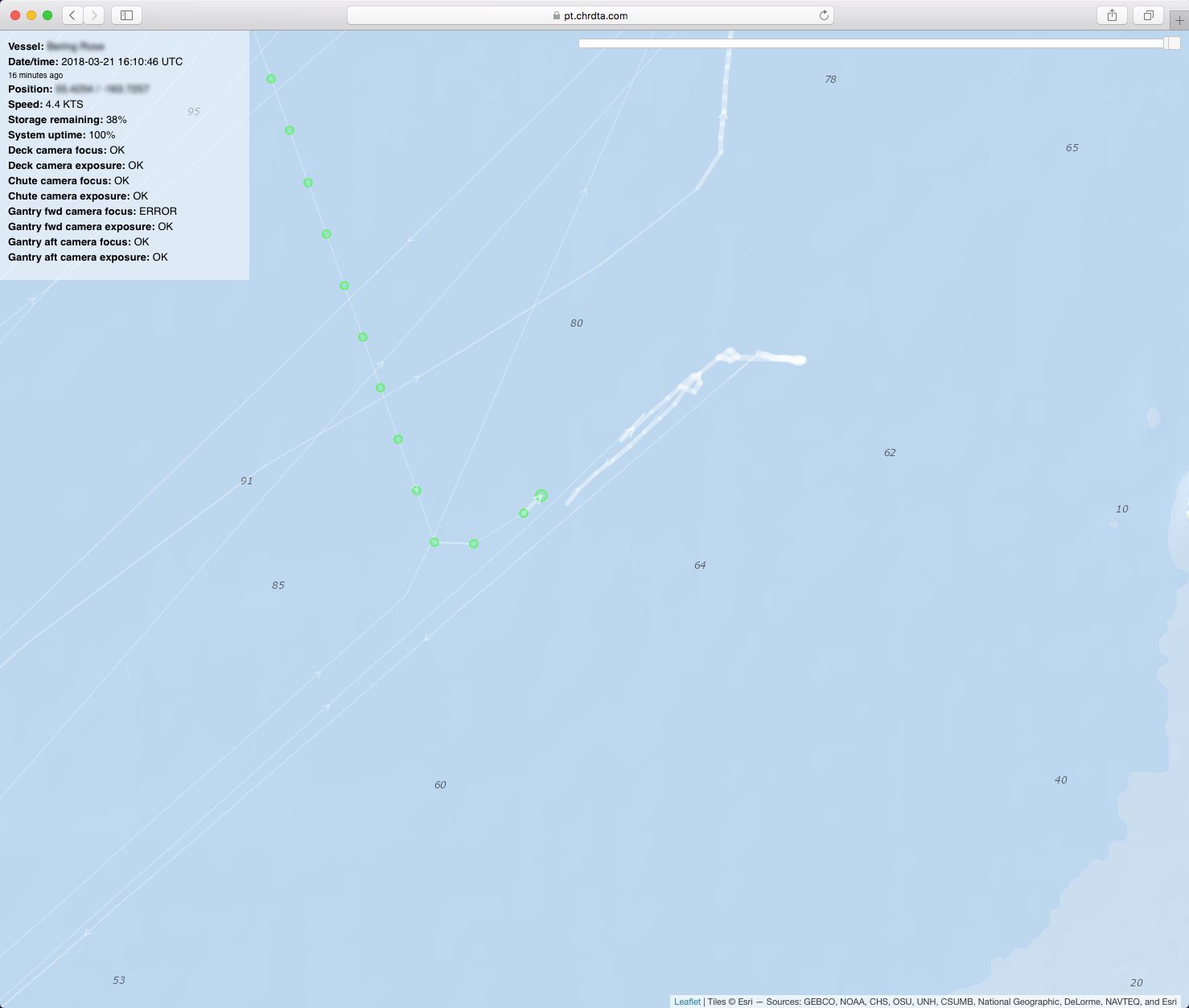
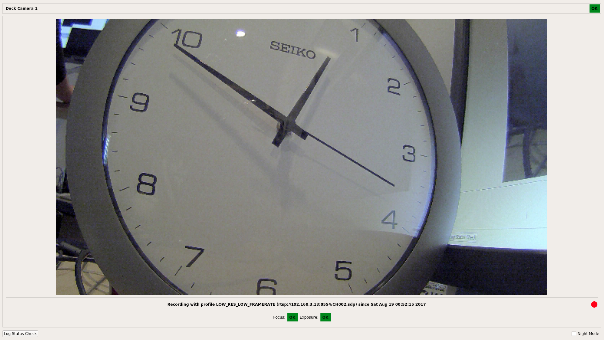
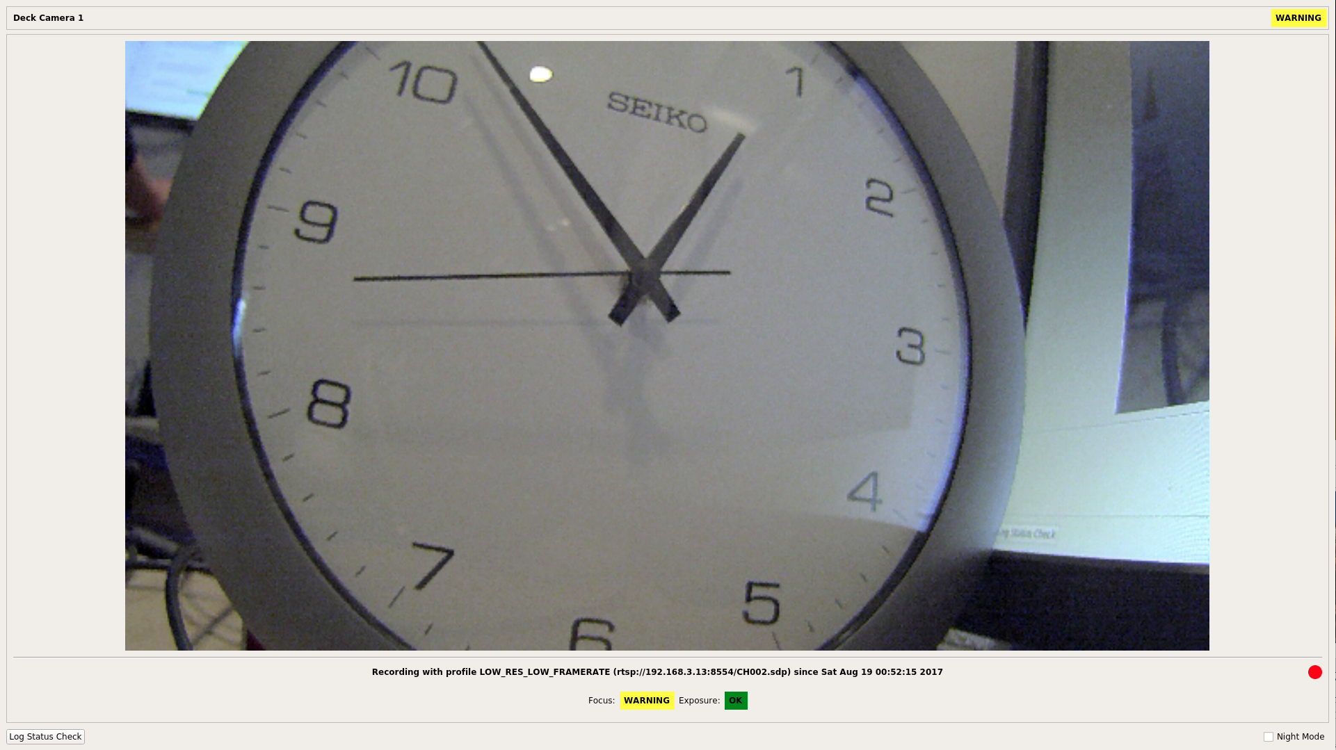
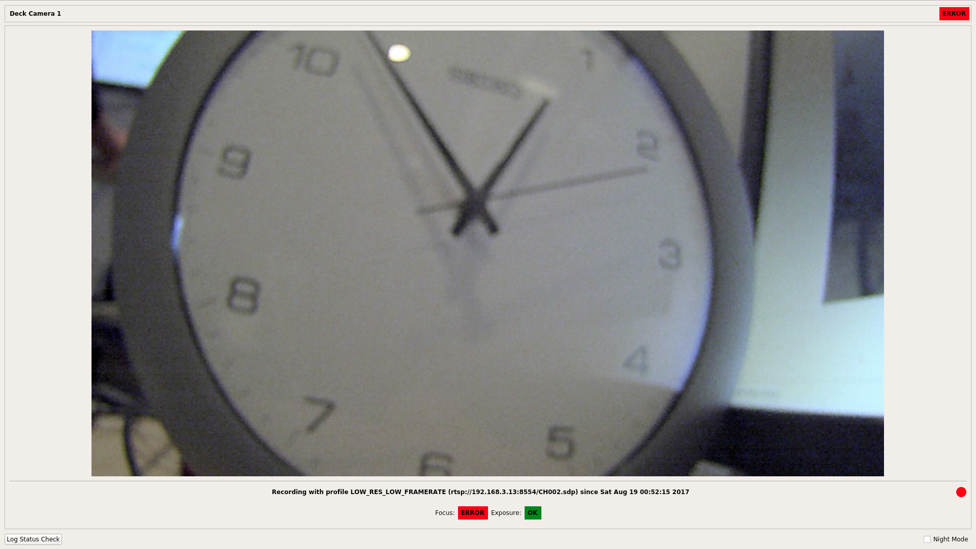
The shipboard component collects EM sensor and/or video data. It triggers video recording based on geospatial or sensor cues. It provides EM system diagnostic information to vessel operators and to shoreside personnel as well via an encrypted Iridium satellite link.
Adaptable to a Wide Range of EM Programs
- Equally suited to generation of catch accounting data or for compliance monitoring
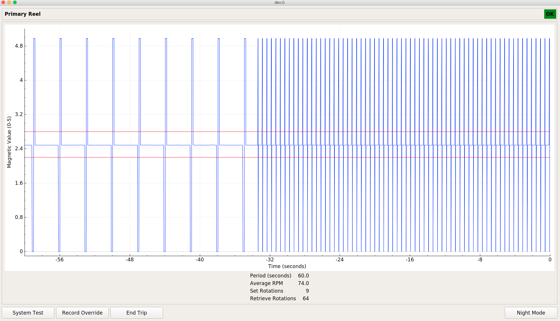
- Drivers are complete for measuring drum rotation speed and direction and the engagement of hydraulic powered equipment using low cost analog to digital converters, Hall effect sensors and pressure transducers
- Any sensor with a 0-5v output can be integrated with minimal effort - relays and/or optocouplers allow for instrumentation of almost any electrical equipment
- All components are configuration driven, so EM programs using already supported sensors, cameras and computer hardware will require no additional software development effort
- Triggering of recording as well as changes to video parameters such as resolution, frame rate and image quality are based on rules involving sensor data, spatial lookups and/or computer vision
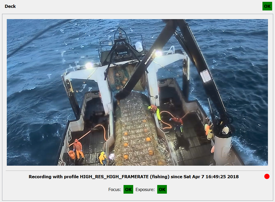
- Flexible camera control using ONVIF allows for capture of video on each channel at a frame rate, resolution and quality ideal for whatever activity is taking place (offloading, transiting, setting gear, hauling gear, sorting catch)
- Consistant use of UTC time accross all system components prevents problems with transits accross timezones and DST offsets
VMS Capabilities Using Iridium Satellite Network
- Provides near real time vessel position, sensor data and EM system health for a few dollars per day
- Works everywhere (on earth)
- Capture data on any interval and report it on any interval
- Queue and retry behavior
- Secure storage of all satellite messages along with EM sensor and video data
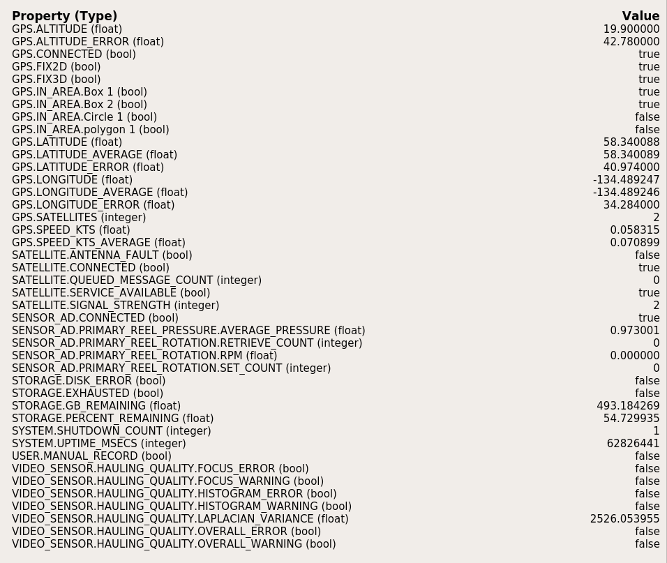
- Bering Sea field trial system captured vessel position, camera focus and exposure, storage remaining and other EM system parameters on a ten minute interval and trasmitted them shoreside once per hour using the Rockblock+ Iridum SBD transceiver. There were no missed transmissions during the four month field trial period.
Hardware and Operating System Flexibility
- Well suited to low power/low cost hardware platforms
- Possible to work within power budgets of 25-35W including two cameras
- Hardware costs of $300-1500 (excluding cameras) are possible using commodity or custom hardware
- Capable of operating as a datalogger without cameras or a user interface
- Easily scales from zero to eight or more cameras
- Shipboard component supports Linux (Ubuntu 16.04 LTS) and Windows 10 (not all capabilities are available in Windows)
- Review component currently supports Windows 10
- C++ is fairly portable, so many other OS and hardware architectures are possible
- Preliminary testing has been done on Linux/ARM, Windows 10/ARM should be possible
Automated video and sensor data analysis can provide significant improvements in the efficiency of summarizing the raw shipboard data and converting it into actionable intelligence. It can perform simple tasks such as identification of segments of video that require review, or marking of sections for random audit in concert with trip logbooks. More sophisticated computer vision and machine learning tools can find fishing activity in video footage and in some cases identify fish to species.
Shipboard Integration of Video Analytics
- Computer vision based recording triggers such as deck activity level or hatch position
- Logging and/or satellite transmission of virtual sensor values such as deck activity level, camera function
- Real time UI feedback for skippers – detection of an out of focus or failing camera
Shoreside Integration of Video Analytics
- Level of deck or sorting area activity
- Fish identification and measurement
- Gear presence/absence detection
- Automated creation of summarized data elements
Source code and a windows build are provided for a prototype motion detection video pre-processor that allows a reviewer to zero-in on periods of high activity in specific areas on deck. It uses various computer vision algorithms to limit false positives from noise, ropes, camera shake etc.
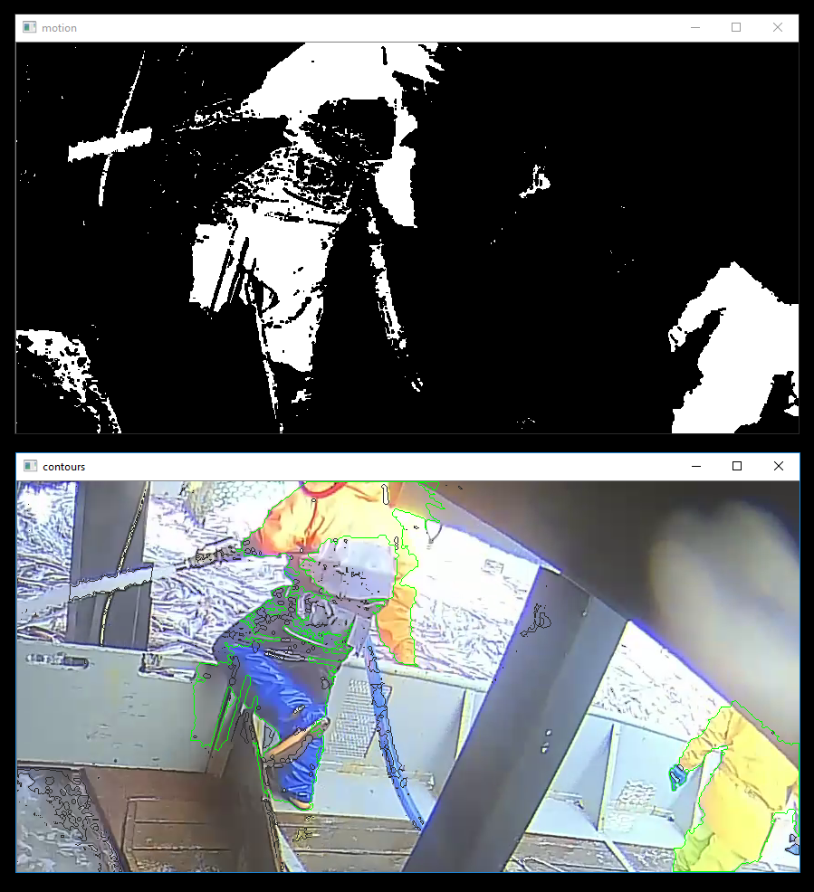
Many other automated analysis tools are currently under development and the software design supports easy integration with them.
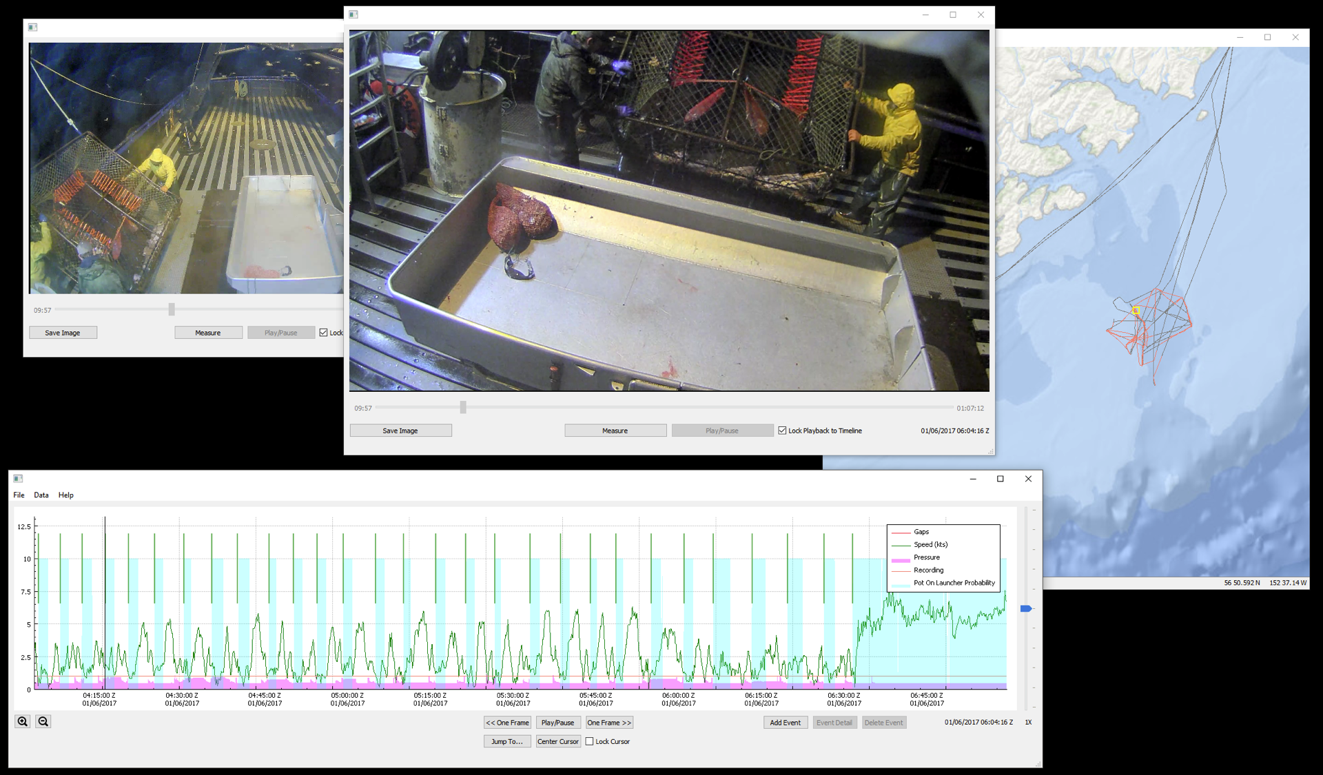
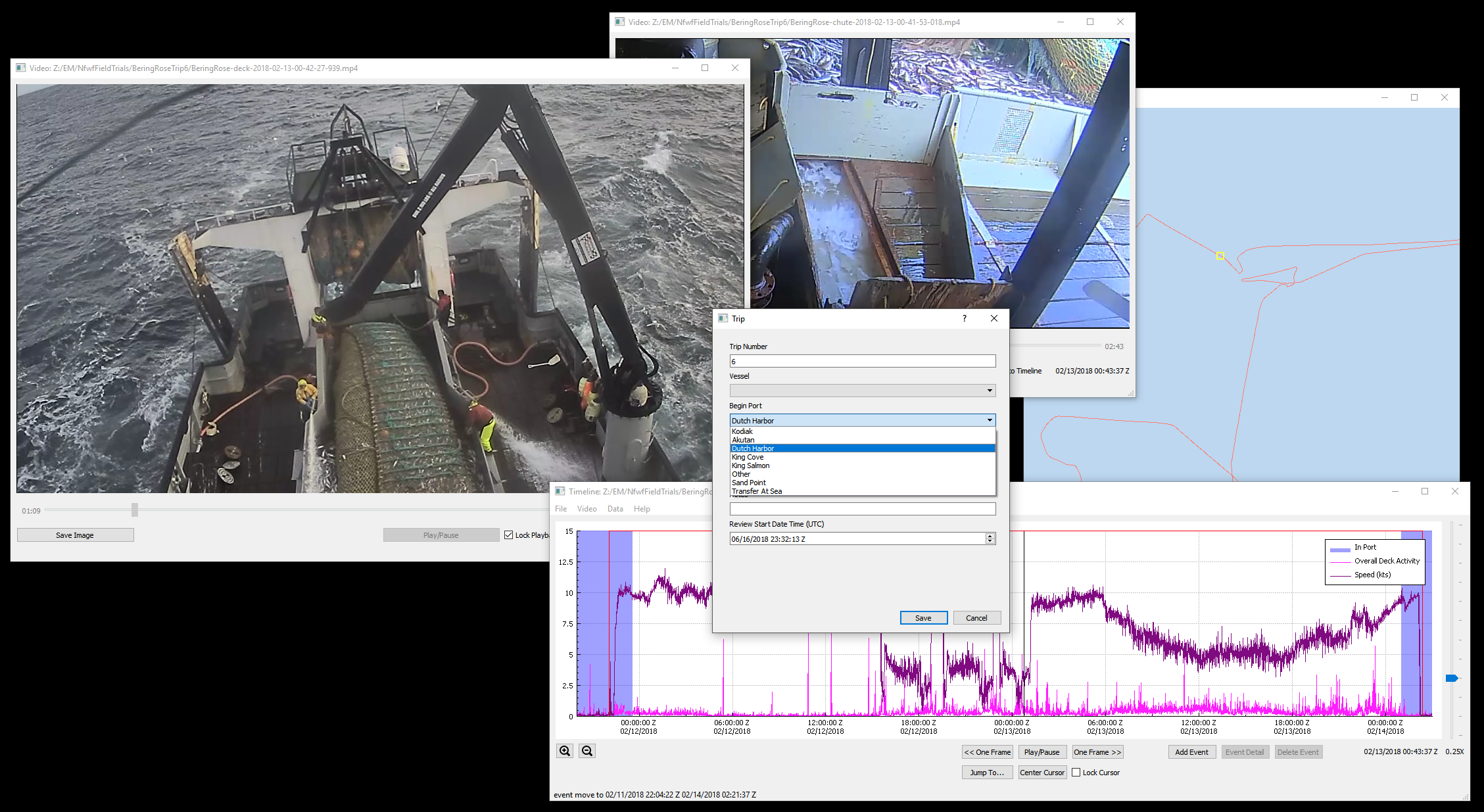
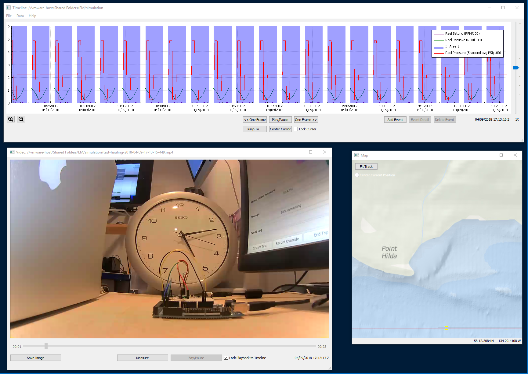
Almost all EM programs still require some level of review by shoreside personnel even after the data has been processed by analytics, and this component facilitates efficient and timely execution of that requirement. The review application itself provides easy access to geospatial, gear sensor and video data, and allows for the annotation and summarization of the data into a form that is useful to fisheries managers, as well as export to databases or other reporting tools. Reviewer data entry is defined by templates such as the one below.
;events
event/1/name = Trip
event/1/marker_type = DURATION
event/1/color = green
event/1/style = LINE
event/1/alpha = 255

event/1/control/1/name = Trip Number
event/1/control/1/required = true
event/1/control/1/type = INTEGER
event/1/control/1/bottom = 0
event/1/control/1/top = 1000

event/1/control/2/name = Vessel
event/1/control/2/required = true
event/1/control/2/type = SELECT
event/1/control/2/values = "1:Vessel 1","2:Vessel 2"

event/1/control/3/name = Begin Port
event/1/control/3/required = true
event/1/control/3/type = SELECT
event/1/control/3/values = "1:Kodiak","2:Akutan","3:Dutch Harbor","5:King Cove","6:King Salmon","7:Other","8:Sand Point","10:Transfer At Sea"
event/1/control/3/default_value = "3:Dutch Harbor"

event/1/control/4/name = End Port
event/1/control/4/required = true
event/1/control/4/type = SELECT
event/1/control/4/values = "1:Kodiak","2:Akutan","3:Dutch Harbor","5:King Cove","6:King Salmon","7:Other","8:Sand Point","10:Transfer At Sea"
event/1/control/4/default_value = "3:Dutch Harbor"

event/1/control/5/name = Log Book Data Available?
event/1/control/5/required = true
event/1/control/5/type = SELECT
event/1/control/5/values = "1:Yes","0:No"

event/1/control/6/name = Notes
event/1/control/6/required = false
event/1/control/6/type = TEXT

event/1/control/7/name = Review Start Date Time (UTC)
event/1/control/7/required = true
event/1/control/7/type = DATE_TIME
| Vessel | Gear | Fishery | Configuration | Approximate Sea Days |
|---|---|---|---|---|
| Bering Rose | Pelagic Trawl | Bering Sea Pollock | Four cameras, vessel speed and location based resoluton and frame rate switching using ONVIF, satellite monitoring | 30 |
| Janas | Demersal Longline | Antarctic Toothfish | Three cameras, hydraulic and line shooter sensors | 80 |
| Karen Evich | Pelagic Trawl | Gulf of Alaska Pollock | Three cameras, hydraulic and rotation sensors | 25 |
| Miss Sarah | Pelagic Trawl | Pacific Hake | Three cameras, hydraulic and reel rotation sensors | 15 |
| Sapphire III | Pelagic Longline | Hawaii Tuna/Swordfish | Two cameras, hydraulic and rotation sensors for two reels | 50 |
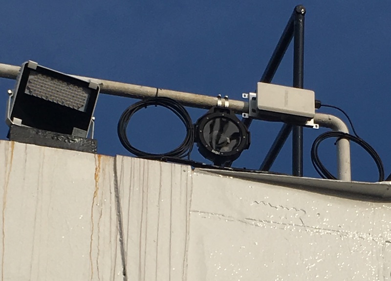
Cameras
Almost any modern IP camera will be compatible with the system or can be made to work with minor code changes. Cameras from Vivotek and Axis seem to be the most suitable after field trials. A subscription to IPVM is a worthwhile investment during the camera selection and testing phase of a project. H265 support will likely be added in future.
Make and models tested (IP camera models change frequently and the links below will likely become stale):- Axis M3045 in Dotworkz BASH housing (bench and field testing)
- Axis M3027 (bench testing)
- Bosch Dinion IP 5000 HD (bench testing) - this camera has a slightly non-standard ONVIF implementation, but code changes have been made to support it
- Geovision VD2400 (bench and field testing)
- Sony SNC-EB600B (bench and field testing)
- Vivotek MD8563-EHF2 (bench and field testing)
- Vivotek FD836BA-HTV (bench testing)
- Vivotek FD8382-EVF2 (bench testing)
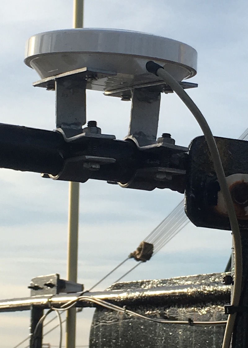
Wireless
To avoid a complicated and expensive wire run on one of the field trial vessels, a Trendnet wireless bridge was used to connect cameras mounted on the aft gantry to the EM system in the wheelhouse. The distance was approximately 100 feet with a clear line of sight. The available bandwidth was just sufficient for two 1080 @ 15fps streams. Even in heavy snow, rain and icing conditions, no notable connectivity problems were experienced.While we have made efforts to reduce complexity wherever possible, we have made flexibility an even higher priority. Software designed to operate with this degree of flexibility is necessarily somewhat involved to configure. We have included a set of examples to help demonstrate some of the possible configurations, but each EM program will have specific requirements and will require integration and testing. We expect that this software is useful as a foundation, but do not expect it to be a "drop-in" fit for any particular application. Another key design principle for this project was to use approaches that would scale effectively to deployment on larger fleets, at the expense of making it easy to deploy for smaller programs. Some of these decisions were to prioritize development of the shipboard component on Linux, the use of purely text based configuration, and an agnostic approach to file systems and disk management allowing for a wide range of storage hardware.
To configure and run the software on the bench from a prebuilt binary will require a basic understanding of IP cameras, RTSP streaming, PKI encryption and Linux or Windows systems administration, as well as general familiarity with EM concepts. Development will additionally require experience with QT, C++, and Linux or Windows software development. Bootstraping a Linux development environment is fairly straightforward (can be performed with the script linked below), but Windows will be more complicated. For historical reasons, the structure of these projects is not as uniform as one would like, but ongoing simplification of the build process and consolidation in to a single source tree and build process will take place at some point in the future.
This software platform has been widely adopted and is in production use accross the US. In the last several years, significant improvements and additions have been made to the source code that are not reflected in this document, however it is still broadly applicable.
Linux shipboard install and run using downloaded build
- All Linux deployment targets start with a minimal
install of Lubuntu
16.04 LTS. Additional information regarding minimal
installations of Lubuntu is available here.
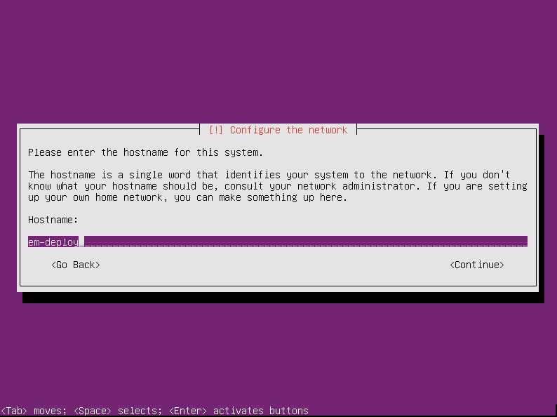
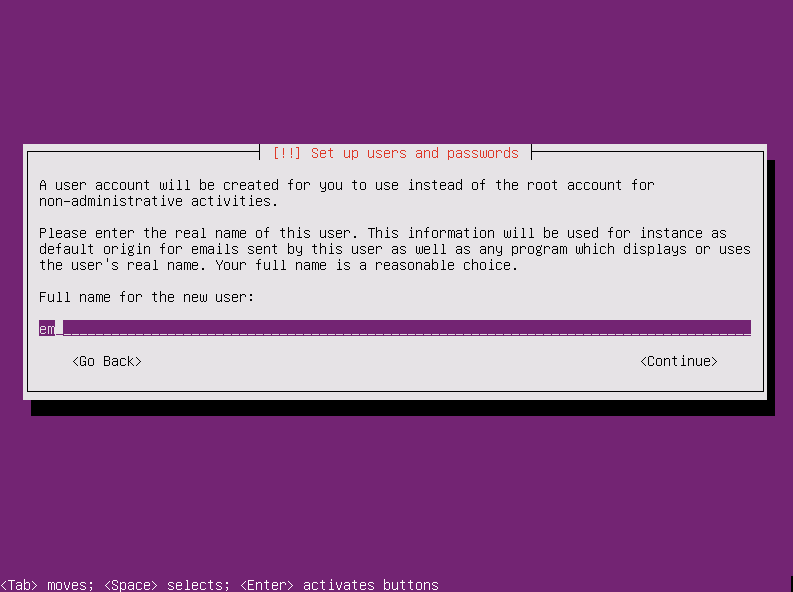
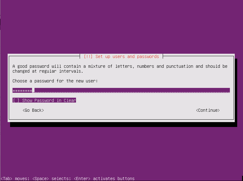
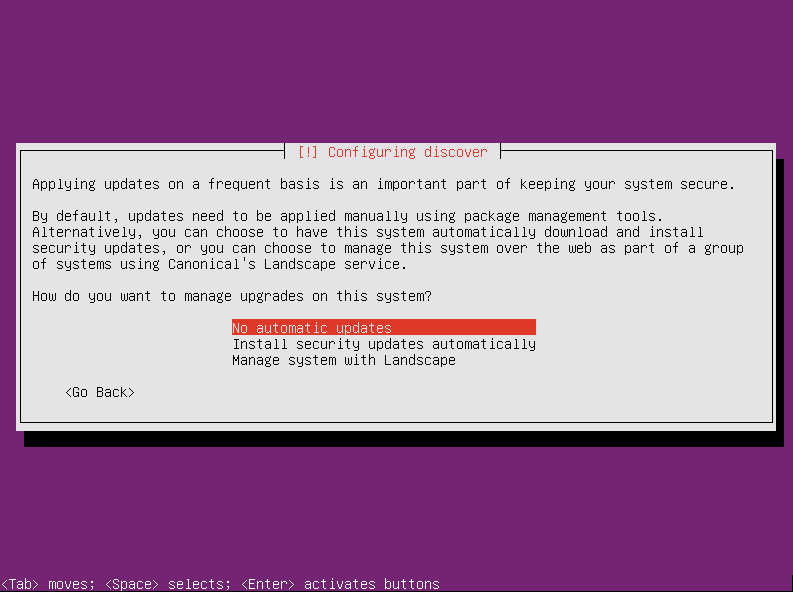
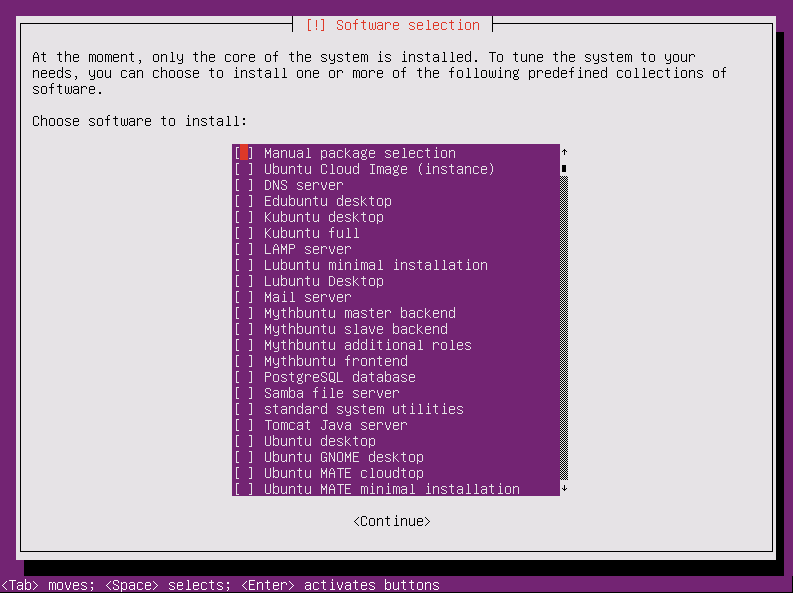
Install using default values, except that you should unselect
all packages on the software selection page. A network
connection is required. Pick any hostname, username and password
that you like. Probably best not to enable automatic updates.
You may wish to dd a copy of the disk you've just installed on
for future use.
- Login as the user you created at install time
- sudo su -
- apt install wget wget https://tinyurl.com/ycnv3lzn -O deploy.tar.bz2 (this tiny url currently points to https://bitbucket.org/fisherieselectronicmonitoring/shipboard/downloads/deploy-ubuntu-16.04-64-20180529-3a245f956bd2.tar.bz2 and will be updated to point at the latest posted build)
- tar -xvf deploy.tar.bz2
- cd deploy
- ./install16.04 example-deploy (you'll probably want to take a look at this script before you run it so as to get an idea what it does)
- Reboot and the shipboard user interface should start
automatically with no cameras, no GPS and 0% remaining storage
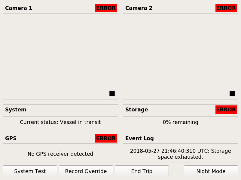
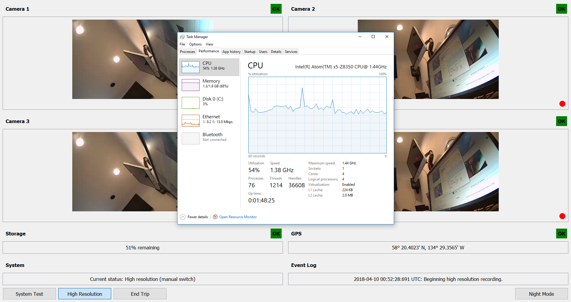
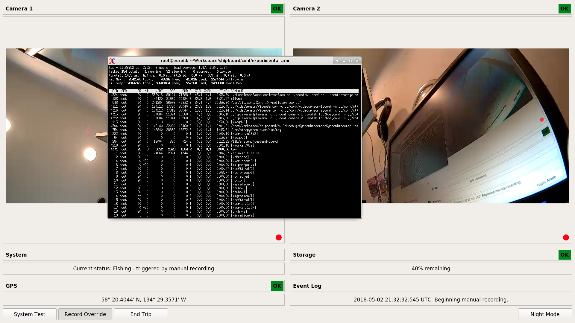
- The "example-deploy" configuration defines two cameras with focus and exposure monitoring and GPS. Both cameras record at low resolution and frame rate until the "Manual Record" button is toggled on, at which point they will switch to a high resolution and frame rate. No satellite reporting or other sensors are defined. To complete the demonstration you'll need two IP cameras, a gpsd compatible GPS and a USB disk or thumb drive. A terminal window will be behind the user interface.
- Format the USB disk using and label it "EM_DATA_0" - for example: mkfs.ext4 -LEM_DATA_0 /dev/sd[X]1
- Edit /etc/default/gpsd to point to your GPS device and restart gpsd service gpsd restart
- Edit the following files in /opt/em/conf:
camera-1.conf
ipc_uri: "ipc:///tmp/camera-1.sock"
trace_log_path: "/tmp"
trace_log_stream_name: "tracelog-ipcamera-1"
stream_name: "camera1"
camera_address: "192.168.0.201" #set this to the IP address of your first camera
connection_retry_period_secs: 5
first_frame_timeout_msecs: 20000
other_frame_timeout_msecs: 1000
write_sps_pps: false #set this to true if you are using a camera that doesn't embed the H264 SPS and PPS in the RTPS stream itself (Axis)
video_profile {
    identifier: "LOW_RES_LOW_FRAMERATE"
    description: "transit"
    rtsp_path: "/live.sdp" #set this to the RTSP url path for your low resolution stream
    max_file_size_mb: 512
}
video_profile {
    identifier: "HIGH_RES_HIGH_FRAMERATE"
    description: "fishing"
    rtsp_path: "/live2.sdp" #set this to the RTSP url path for your high resolution stream
    max_file_size_mb: 512
}
camera-2.conf
ipc_uri: "ipc:///tmp/camera-2.sock"
trace_log_path: "/tmp"
trace_log_stream_name: "tracelog-ipcamera-2"
stream_name: "camera2"
camera_address: "192.168.0.202" #set this to the IP address of your second camera
connection_retry_period_secs: 5
first_frame_timeout_msecs: 20000
other_frame_timeout_msecs: 1000
write_sps_pps: false #set this to true if you are using a camera that doesn't embed the H264 SPS and PPS in the RTPS stream itself (Axis)
video_profile {
    identifier: "LOW_RES_LOW_FRAMERATE"
    description: "transit"
    rtsp_path: "/live.sdp" #set this to the RTSP url path for your low resolution stream
    max_file_size_mb: 512
}
video_profile {
    identifier: "HIGH_RES_HIGH_FRAMERATE"
    description: "fishing"
    rtsp_path: "/live2.sdp" #set this to the RTSP url path for your high resolution stream
    max_file_size_mb: 512
}
videosensor-1.conf
ipc_uri: "ipc:///tmp/videosensor-1.sock"
reporting_frequency_msecs: 100
stream_url: "rtsp://192.168.0.201/live.sdp" #set this to the RTSP url path that you'd like to use for focus and exposure monitoring on your first camera - lower bitrate streams will consume less CPU and high framerate is of little benefit
trace_log_path: "/tmp"
trace_log_stream_name: "tracelog-video-sensor-1"
visualization_socket: "ipc:///tmp/videosensor-frame-1.sock"
frame_timeout_msecs: 10000
frame_width: 640 #set this to the horizontal resolution of the RTSP stream above
frame_height: 360 #set this to the vertical resolution of the RTSP stream above
resize_frame: false
connection_retry_period_secs: 5
...
videosensor-2.conf
ipc_uri: "ipc:///tmp/videosensor-2.sock"
reporting_frequency_msecs: 100
stream_url: "rtsp://192.168.0.202/live.sdp" #set this to the RTSP url path that you'd like to use for focus and exposure monitoring on your second camera - lower bitrate streams will consume less CPU and high framerate is of little benefit
trace_log_path: "/tmp"
trace_log_stream_name: "tracelog-video-sensor-2"
visualization_socket: "ipc:///tmp/videosensor-frame-2.sock"
frame_timeout_msecs: 10000
frame_width: 640 #set this to the horizontal resolution of the RTSP stream above
frame_height: 360 #set this to the vertical resolution of the RTSP stream above
resize_frame: false
connection_retry_period_secs: 5
...
ui.conf
...
ip_camera_module_display {
    identifier: "CAMERA_1"
    pane: "CAMERA_1"
    title: "Camera 1"
    preview_url: "rtsp://192.168.0.201/live.sdp" #set this to the RTSP url path that you'd like to use for preview in the UI - lower bitrate streams will consume less CPU
    report_video_quality: true
    video_quality_properties: "CAMERA_1_SENSOR.QUALITY"
}
ip_camera_module_display {
identifier: "CAMERA_2"
pane: "CAMERA_2"
title: "Camera 2"
preview_url: "rtsp://192.168.0.202/live.sdp" #set this to the RTSP url path that you'd like to use for preview in the UI - lower bitrate streams will consume less CPU
report_video_quality: true
video_quality_properties: "CAMERA_2_SENSOR.QUALITY"
}
...
You will want to review the conf/example-annotated configuration before embarking on more significant modifications. - After a reboot you should see "OK" for all system components.
Windows shipboard install and run using downloaded build
All Windows development and testing to date has taken place using Windows 10 Professional or Enterprise LTSB, but it is likely other recent Windows versions will work also.- Download and unzip https://bitbucket.org/fisherieselectronicmonitoring/shipboard/downloads/deploy-windows-10-32-20180421-80ed1e1a3038.7z (7zip is available here)
- Open the deploy/scripts directory and run the tmpSetup.bat batch file to create some temporary folders for data storage.
- Run the run.bat batch file to start the program. If you are missing the 32 bit Visual C++ runtimes, the installer is located at deploy/bin/vcredist_x86.exe
- This deployment has a very simple configuration with manual record
triggering for a single camera. To complete the configuration,
edit the following files in /deploy/conf:
camera-vivotek-fd836ba.conf
ipc_uri: "ipc:///tmp/camera1.sock"
trace_log_path: "/tmp/logs"
trace_log_stream_name: "tracelog-ipcamera-camera1"
stream_name: "camera1"
camera_address: "192.168.0.201" #set this to the IP address of your camera
connection_retry_period_secs: 5
first_frame_timeout_msecs: 20000
other_frame_timeout_msecs: 1000
write_sps_pps: false #set this to true if you are using a camera that doesn't embed the H264 SPS and PPS in the RTPS stream itself (Axis)
video_profile {
    identifier: "HIGH_RES_HIGH_FRAMERATE"
    description: "high resolution high framerate"
    rtsp_path: "/live.sdp" #set this to the RTSP url path for the stream you'd like to use
    max_file_size_mb: 512
}
ui.conf
...
ip_camera_module_display {
    identifier: "CAMERA1"
    pane: "CAMERA1"
    title: "Camera 1"
    preview_url: "rtsp://192.168.0.201/live.sdp" #set this to the RTSP url path that you'd like to use for preview in the UI
    report_video_quality: false
}
eventlog_display {
    pane: "EVENTLOG"
    title: "Event Log"
}

user_action {
    action_identifier: "SYSTEM_TEST"
    button_text: "System Test"
    dialog_text_file_path: "../../../TestData/SelfTest.html" #optionally set this to point to a text or HTML file that describes the self test process to the end user
    toggle: false
}
...
Windows preprocessor install and run using downloaded build
- Download and unzip https://bitbucket.org/fisherieselectronicmonitoring/preprocessor/downloads/deploy-windows-10-64-20180412-c77670c21c68.7z (7zip is available here)
- Edit at least the region of interest values in deploy/settings.ini - you will likely want
to alter other values depending on the frame rate and resolution
of your input footage.
[preprocessor]
;contours with aspect ratios greater than this are excluded - catches swinging ropes, shaking rails that are often false positives
countour_max_aspect=8
;ignore contours smaller than this percent of the ROI (mostly noise)
contour_vs_roi_min_percent=.001
;if this much or more of the ROI is moving we are at 100%
contour_vs_roi_max_percent=.05
;averge the motion level over how many frames
amplitude_rolling_avg_window=40
;show some visual output regarding the process. if the visual windows have focus, any key excpet esc will pause, esc will quit
show_diagnostic_window=true
;how far from the top and left sides to crop as a percentage: .5 = crop in half way accross the frame
roi_x_percent=.25
roi_y_percent=.50
;width of the ROI as a percentage: .5 = half the frame width or height
roi_width_percent=.40
roi_height_percent=.45
;blur before finding contours to reduce noise
blur_kernel_size=3
;output file is produced in the same directory as the video-toc file
output_file_name=deck_activity.csv
- Run the preprocessor from the command line as follows: DeckActivityPreprocessor.exe settings.ini
[path to video table of contents file (.video-toc)] This table
of contents file is a CSV file with the following fields
[relative path and filename],[file start UTC milliseconds],[file
end UTC milliseconds]:
Test_Vessel_1234-gantry_forward-2018-02-11-23-38-49-241.mp4,1518392329241,1518395123486
Test_Vessel_1234-gantry_forward-2018-02-12-00-25-25-491.mp4,1518395125491,1518416037192
Test_Vessel_1234-gantry_forward-2018-02-12-06-13-57-528.mp4,1518416037528,1518448195918
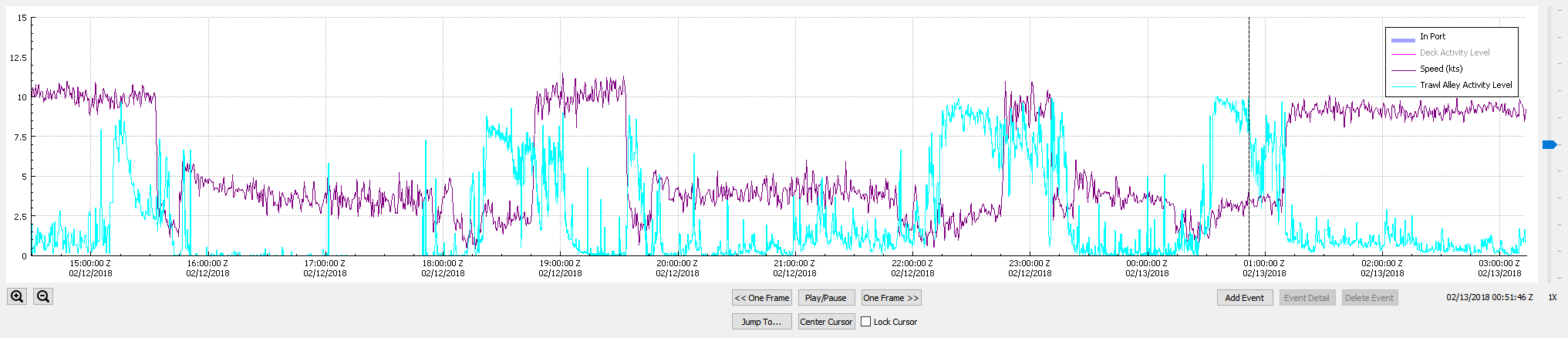
- The output file (the name of which is specified in the settings.ini file above) will be created in the same directory as the video table of contents file and is in the form [UTC seconds/fractional seconds],[activity level ranging from 0-1]. This output file can be integrated into the data review process in various ways, but most likely would be treated as a "virtual sensor" in the review software.
Linux shipboard development environment setup
- Start with the same minimal Lubuntu 16.04 LTS install as described in the "Linux shipboard install and run using downloaded build" section above
- Login as the user you created at install time
- sudo su -
- apt install wget
- wget https://tinyurl.com/y8uv233m -O devSetup16.04 (this tiny url points to https://bitbucket.org/fisherieselectronicmonitoring/shipboard/raw/default/scripts/devSetup16.04)
- chmod u+x devSetup16.04
- ./devSetup16.04 (you'll probably want to take a look at this script before you run it so as to get an idea what it does)
- If you run into problems rm -rf /root/setup and start again
- Once the devSetup16.04 script is complete, reboot the machine and the QT IDE (QtCreator) and a terminal should start automatically along with X11. The project will have been checked out into /root/Workspace/shipboard/.
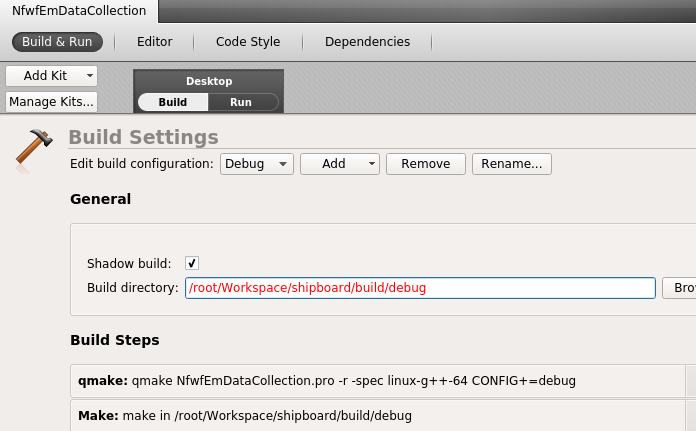
- Configure the project with defaults in QtCreator, but switch the
debug build directory to /root/Workspace/shipboard/build/debug
and your release build directory to /root/Workspace/shipboard/build/release
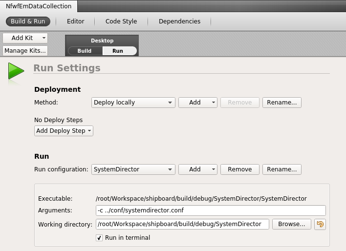
- Set the run arguments for the System Director to -c ../conf/systemdirector.conf
- cd /root/Workspace/shipboard/scripts
- ./tmpSetup (this creates some ephemeral target directories in tmp and copies around encryption keys)
- ./setConfig example-annotated (this deletes and re-creates a symlink to an example config)
- Build the "Shared" project first, and then build "NfwfEmDataCollection"
- Once you have successfully built the project, edit conf/example-annotated to match the desired hardware configuration that you are developing for.
- /root/Workspace/shipboard/scripts/killAll will kill all modules once a test run is complete.
Windows shipboard development environment setup
Building on Windows requries also building from source most of the assocaited libraries as well and is too involved to address in this document.Futher configuration (Linux and Windows)
Shipboard configuration is accomplished using the Google protocol buffers library (protobuf). Core system configuration is managed in the system director configuration file. It references each of the optional “modules” in the system such as the ADC and GPS sensor modules and the user interface module. Many of these modules have their own configuration files as well. The system director configuration defines one or more “triggers” that indicate what state the system should be placed in – e.g. is the vessel transiting or fishing? Each trigger has a logical condition that evaluates to true or false. The triggers define a precedence so that if more than one trigger evaluates to true, the higher precedence trigger will be in effect. Triggers have one logging profile identifier, one recording profile identifier and one satellite transmission profile. Blank logging and satellite profiles are allowed, but if any triggers define a recording profile, all triggers must define one – this is because cameras must be actively “turned off” if recording is not desired. The system director configuration also defines the logging, satellite transmission and recording profiles themselves. Recording profiles define states for each of the cameras in the system, logging profiles define the template used to create sensor logs.Processing data for review (Linux and Windows)
Data is decrypted and processed for review using the Tools/FileProcessor/FileProcessor binary. It can be run (or scripted) from the command line, or use the Tools/FileProcessorGUI/FileProcessorGUI binary to run interactively.Windows review install and run using downloaded build
All Windows development and testing to date has taken place using Windows 10 Professional or Enterprise LTSB, but it is likely other recent Windows versions will work also.- Download and unzip https://bitbucket.org/fisherieselectronicmonitoring/review/downloads/deploy-windows-10-64-20181120-66beea658ca6.7z (7zip is available here)
- The deploy/templates directory contains several examples of project specific configurations - example-annotated.ini is a good place to start
- This RTF document describes the optional and requried fields used to load EM datasets from a variety of source systems
- Run the Review.exe executable to start the program
- Set the template you want to use with the File->Set Template menu, and then select a folder containing an EM dataset using File->Open.
- The review software is intended to be primarily keyboard driven
during the review process. Mouse and key commands are as follows.
A link to additional help is provided in-application - program implementers would likely setup their
own online documentation site that would cover both software operations and review protocols.
Mouse
	Timeline
		double left click sets cursor position
		double right click starts and completes drawing a data entry event with a duration
		mouse wheel zooms in on mouse pointer
		left click on legend items shows and hides sensor plots
		left click on sensor events and data entry events selects them

	Video
		mouse wheel zooms

	Map
		mouse wheel zooms
		double left click sets cursor position

	Measurement
		double left click sets corners for rectification (must be drawn clockwise)
		double right click sets measurement points - click fast to make multi-segment lines
		left click and drag to adjust any points (rectification, calibration and measurement)
		double middle click to add additional calibration lines


Key commands used to manage user created events - only available when the timeline window has focus
	Key_Delete: delete selected event
	Key_Return: open selected event
	Key_Enter: open selected event
	Key_Slash: add point in time marker
	Key_Up: jump to previous data entry event
	Key_Down: jump to next data entry event
	Key_Left: jump to next sensor event (such as RFID tag read)
	Key_Right: jump to previous sensor event
	Key_Escape: deselect everything and cancel drawing of duration event
	Key_J: jump to related event
	Key_A: adjust the left boundary of selected duration event
	Key_S: adjust the left boundary of selected duration event
	Key_Apostrophe: adjust the position of selected event
	Key_Period: start and stop creation of duration event


Application wide playback control keys - will work regardless of which window has focus
    	Playback speed
		Key_Space: toggle between play and pause
		Key_R: decrease speed one step
		Key_T: 1x
		Key_Y: increase speed one step

	Jump forward and backward
		Key_1: jump back 5 seconds
		Key_2: jump back 3 seconds
		Key_3: jump back 1 second
		Key_4: jump back 1/2 second
		Key_5: previous frame
		Key_6: next frame
		Key_7: jump forward 1/2 second
		Key_8: jump forward 1 second
		Key_9: jump forward 3 seconds
		Key_0: jump forward 5 seconds
Trip simulation
Python and Arduino code to simulate GPS position, reel rotation and hydraulic pressure is available in the "simulation" directory in source tree. It is based on the GPSFake component of the gpsd service, so it will work on Linux only. Contact the project developers below for more information.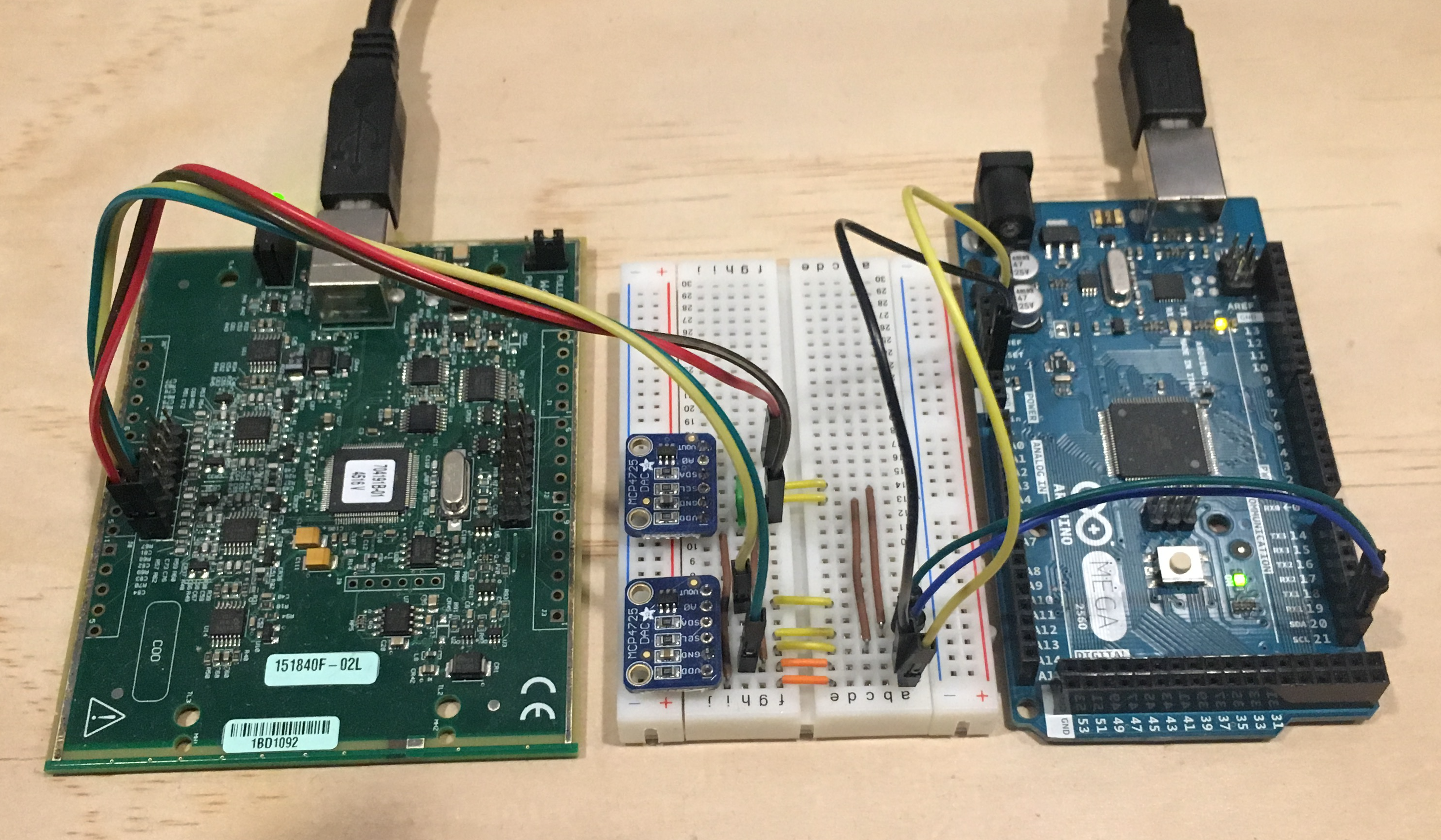
Shapefiles
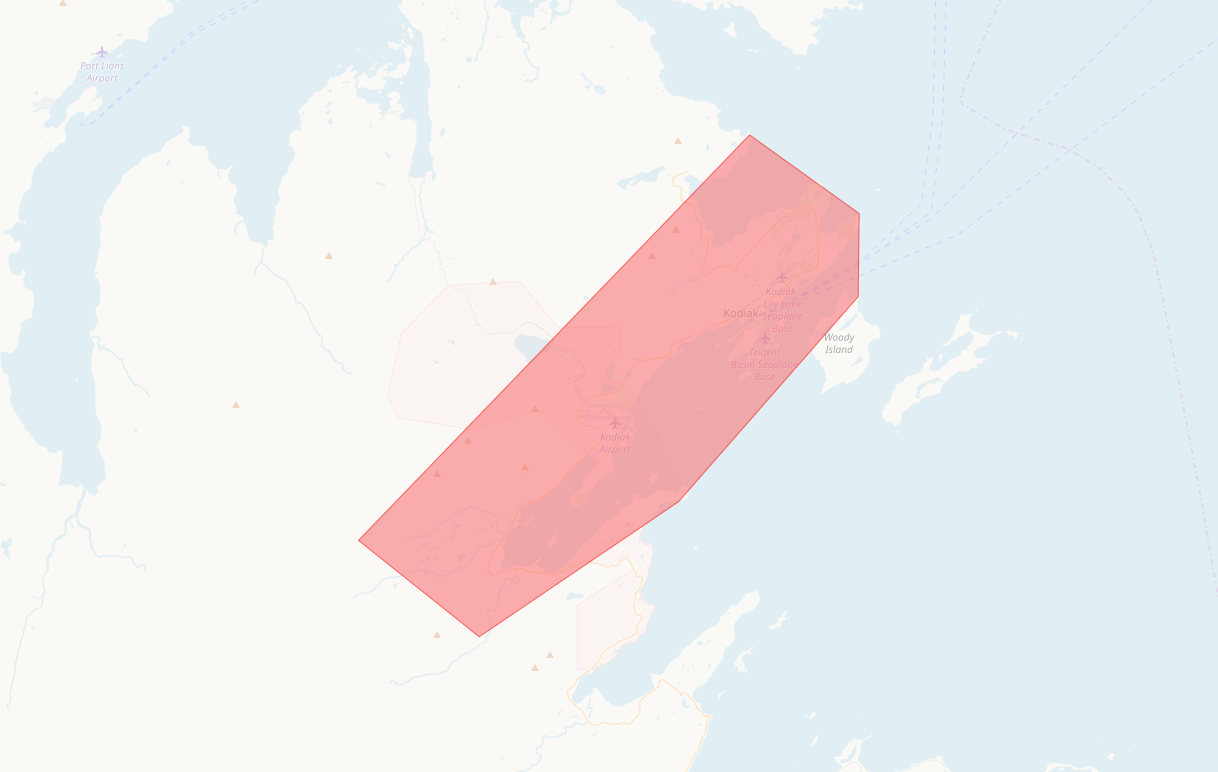
Shapefiles must be of polygon type with a CRS of EPSG 4326 and each shape must have a "name" attribute. More than one shape can share the same value for a given name in which case rules made against this shape will evaluate true if the reported position is within any shape with that name.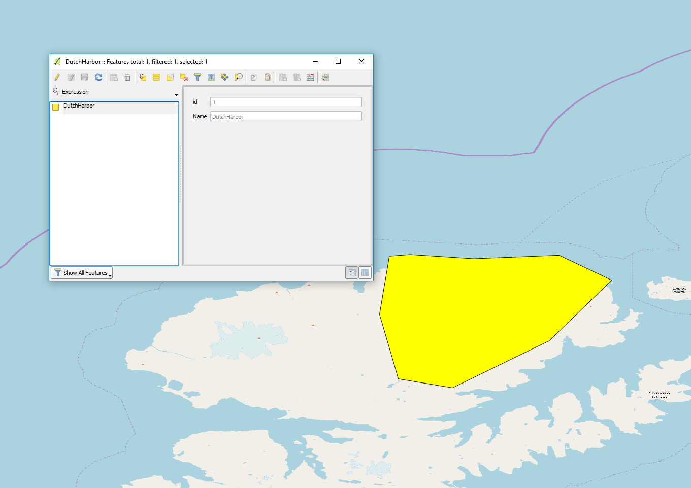
The following trigger will end recording when the vessel is in port and will presume that the vessel is not in port if no GPS fix is available. The rule will no longer evaluate to true once the vessel has been out of port for one minute.
trigger {
    identifier: "PORT"
    description: "In port"
    condition: "$GPS.IN_AREA.DutchHarbor$"
    failure_mode: FALSE_ON_FAILURE
    precedence: 0
    post_trigger_active_seconds: 60
    satellite_transmission_profile_identifier: "HOURLY"
    sensor_log_profile_identifier: "BASELINE30"
    recording_profile_identifier: "NONE"
    exclusive: false
}
This is an example shapefile covering the port of Kodiak, and several other example and field trial shapefiles are checked into the "testData" directory in the source tree.